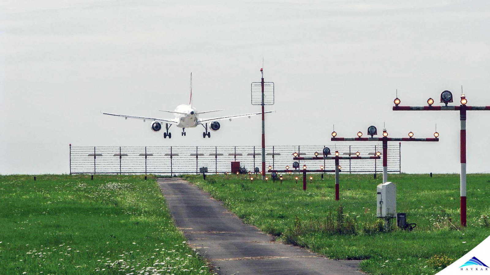


I) Provide directional, distance and glidepath information for safe transition to runway threshold
ILS LOCALIZER CODE
Iv) Middle marker locator ID code consists of the second two letters of the 3-letter LOC identifier Iii) Outer marker locator ID code consists of the first two letters of the LOC 3-letter identifier Ii) A low-powered NDB colocated with the OM and/or MM facilities I) Supplementary, optional component that may be employed to increase safety and utility V) There may be a back-course marker to indicate the back-course FAF Iv) Inner marker ( IM) located at decision height on glidepath for Category II approach Iii) Middle marker ( MM) located approximately 3,500 feet from landing threshold at position where glide-slope centerline is about 200 feet above touchdown zone elevation Ii) Outer marker ( OM) located 4-7 miles from airport near position where aircraft at appropriate altitude will intercept glidepath I) Low-powered transmitters direct signal upward in a small fan-shaped pattern Iv) GS normally 1.4° thick (about 1,500 feet at 10 NM from touchdown, narrowing to just a few feet at touchdown) Iii) GS signal is radiated on front course only (NOT on back course) Ii) Projection angle normally adjusted to 2.5-3.5° above horizontal to intersect the middle marker ( MM) at about 200 feet and the outer marker ( OM) at about 1,400 feet above runway elevation I) Located in a building 750-1,250 feet from approach end of runway, 400-600 feet to one side of centerline
ILS LOCALIZER PLUS
Iv) Audibly identified by "I" plus three-letter designator and includes a voice feature for use by ATC Iii) LOC course width normally 5° (full-scale deflection when aircraft is 2.5° to either side of centerline) Ii) Transmits on odd tenths from 108.1 to 111.95 MHz out to 18 NM away from and 4,500 feet above the antenna site I) Antenna array located beyond opposite end of runway that radiates a field pattern providing left/right guidance along the centerline of the runway (in both directions)

Aircraft Flight Instruments and Navigation EquipmentĢ. When flying an ILS, you track the line formed by the intersection of the glide slope and localizer courses.II. You should observe the initial downward movement of the indicator and lead the descent to intercept the glide slope centerline accordingly. Since your aircraft is usually below the glide slope during the intermediate approach segment, the glide slope indicator will display a full-up needle deflection. This point may or may not be at the middle marker. Although you may reach the decision height at or near the middle marker, the charted MAP for an ILS approach is the point where the glide slope intercepts the decsion height. If you maintain the glide slope for an approach, you should reach the decision height at approximately the middle marker. For the same glide slope angle (usually 3°), you will need a lower rate of descent as your groundspeed decreases, and vice versa. The rate of descent you should maintain primarily depends on your groundspeed. The glide slope gives you vertical guidance on the final approach course. This applies regardless of your direction of travel, whether inbound or outbound on either the front or back course. With an HSI, you can avoid reverse sensing by setting the published front course under the course index. Reverse sensing occurs inbound on the back course and outbound on the front course. When using a basic VOR indicator, normal sensing occurs inbound on the front course and outbound on the back course. This provides the information regarding your alignment with the runway centerline. To help you determine your distance from the runway, the ILS installation may provide DME fixes or marker beacons located along the ILS approach path. You recieve guidance information from ground-based localizer and glide slope transmitters. The ILS installation is made up of several components.


 0 kommentar(er)
